3. DEVICE REGISTRATION
3.1.1.
Go to https://gate.dvc-cloud.com/ as the module owner.
Enter your phone number and the Device ID of your module (the sticker is included in the package).
Create a name for the site you will control.
3.1.2.
Add a list of users who are allowed to open the gate at this site.
Enter their phone numbers and email addresses.
3.1.3.
If needed, create a schedule.
You can set times when the gate or barrier is always open, or always closed and cannot be opened.
3.1.4.
You can also create a list of mobile phone numbers.
Calls from these numbers will activate the output contacts of the DVC GATE module.
Then upload this list to the module memory.
4. CONNECTION
4.1.
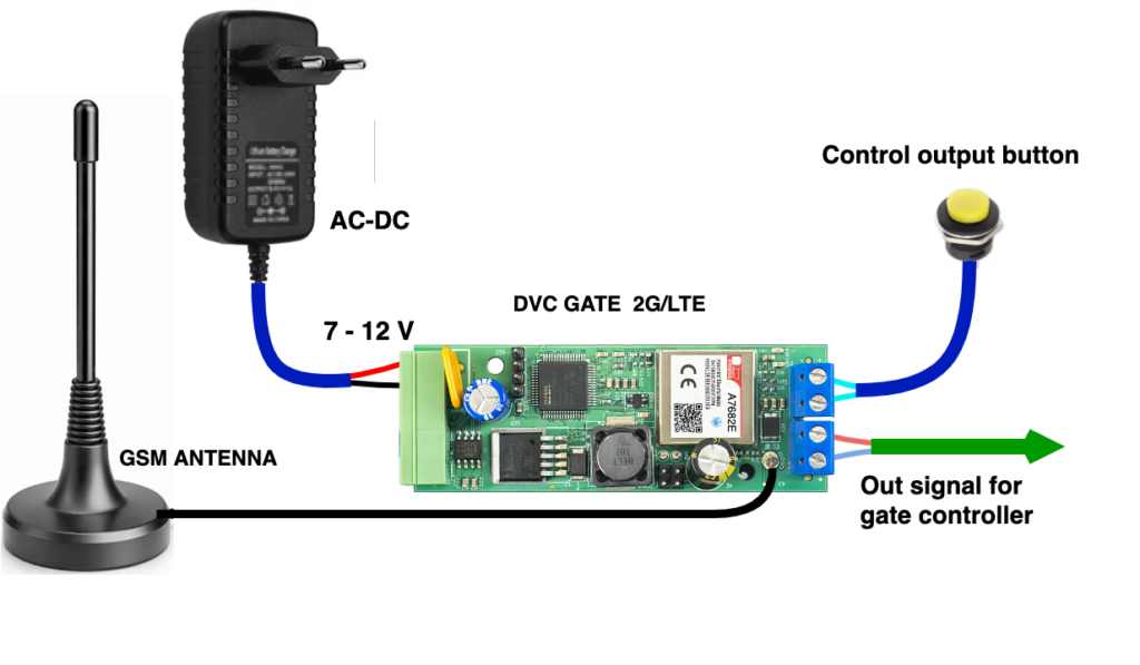
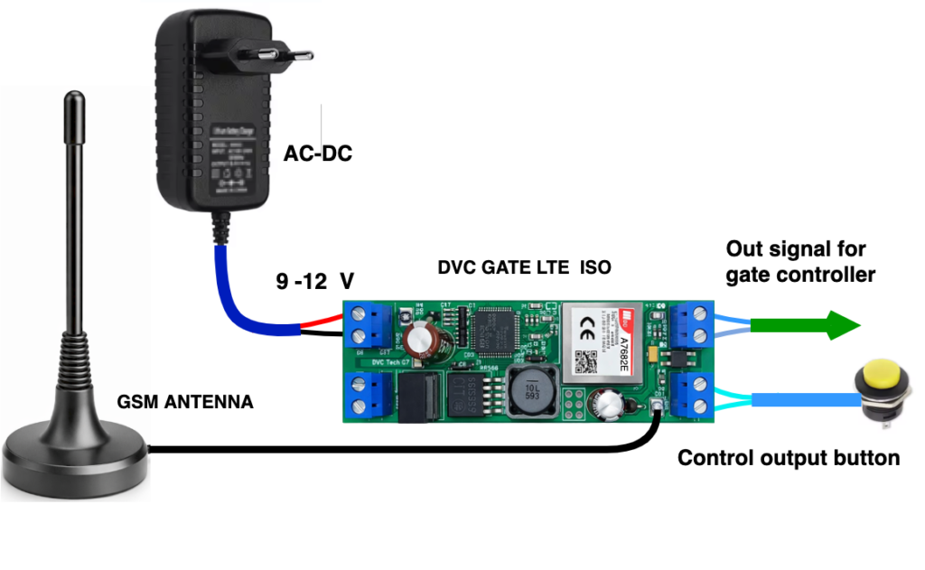
Connect the DVC GATE LTE or Wi-Fi module according to the wiring diagram in this manual.
4.2.
Connect the module output contacts to the control input of the gate or barrier controller (button type / dry contact type).
When using DVC 2G / LTE GATE, the open collector output can be connected directly to the gate controller input that is controlled by “0”, or you can use an external relay.
4.3.
Insert the SIM card into the SIM holder on the back side of the module board and apply power:
4.4.
After 30 seconds, the module will connect to the service and will be ready to work.
4.5.
You can test gate control by pressing the “Test” button on your account page.
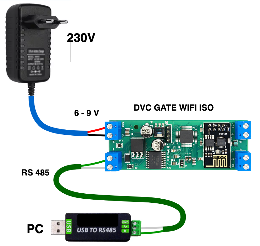
5. SETTING UP DVC GATE WIFI ISO CONNECTION TO WI-FI
5.1.
Download the DVC P)OM terminal program from:
https://division.business/download-dvc-configurator/
Install and run it on Windows OS.
The wiring diagram for DVC GATE Wi-Fi ISO setup to connect to the Wi-Fi network is shown in Fig. 4.