DVC POINT
RS485 — TCP/IP Interface / modem
Technical certificate
Modems
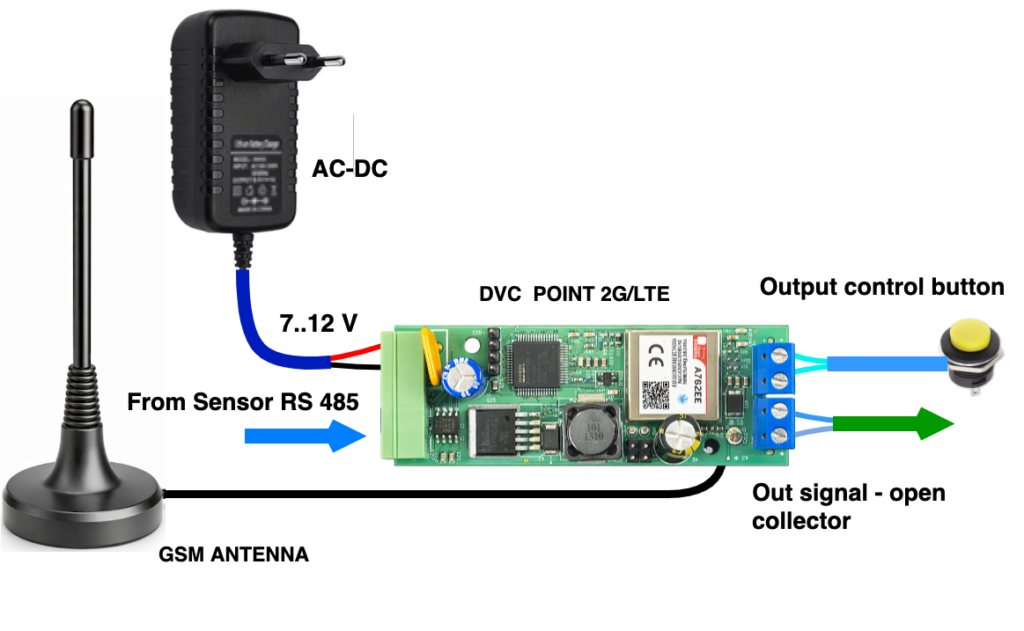
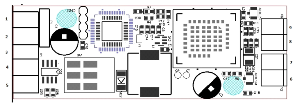
DVC POINT 2G / 2G GPS
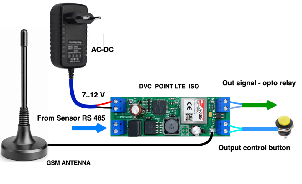
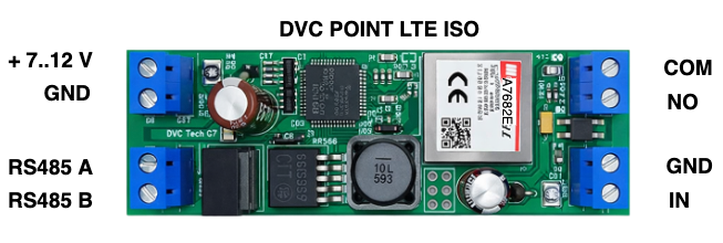
DVC POINT LTE / LTE ISO
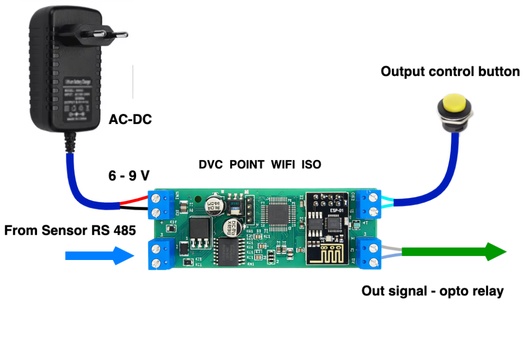
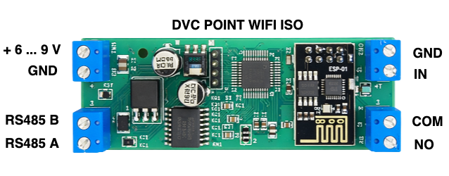
DVC POINT Wi-Fi ISO
Table of Contents
Purpose and Scope of Use ………………………………………………………..3
Functional Features …………………………………………………………………….3
Technical Specifications ……………………………………………………………..4
Pin Assignment …………………………………………………………………………….5
Service Messages …………………………………………………………………………7
Command Protocol ………………………………………………………………………7
Preparation for Setup ……………………………………..…….… …………… 12
Setup and Registration …….……………………………………………………12
Installation and Maintenance…………………………………………………….14
Package Contents ………………………………………………………………………..14
Storage and Transportation Conditions…………………………………. 15
Warranty Obligations ………………………………………………………………….15
1. PURPOSE AND SCOPE OF APPLICATION
This instruction is intended for technical specialists in the fields of automation, dispatching, and engineering equipment monitoring.
The DVC POINT series modems (2G*, 2G-GPS*, LTE, LTE ISO, Wi-Fi ISO) are universal industrial controllers designed to establish a transparent data transmission channel between the RS-485 interface and a TCP/IP network.
ATTENTION! For functionality testing, all modems are supplied with preconfigured settings:
IP: 203.161.41.45
PORT: 6050
and are ready to connect to the DVC CLOUD service: https://dvc-cloud.com/To use the modem in your own projects, you must connect and configure it to your own server (IP address, port, etc.) in accordance with this manual.
This modem series is a key component in Smart City systems and is designed for industrial and home automation systems, dispatching, engineering equipment monitoring, and remote data collection from meters and sensors. They are also used for controlling gates and barriers. Connection diagrams for DVC POINT are provided at the end of this manual.
General specifications for all models:
1 × RS-485 port
1 × digital input
1 × switched output
Model-specific features:
2G / 2G-GPS / LTE: Open-collector output type
LTE ISO / Wi-Fi ISO: Optically isolated RS-485 interface, output opto-relay (load up to 400V / 150 mA)
* When using DVC POINT 2G / 2G-GPS models in your projects, ensure that the GSM operator supports the 2G network.
2. FUNCTIONAL FEATURES
The main function of the modem is to transmit data in both directions without changing the packet content.
Communication channels (depending on the model): 2G, 4G (LTE), Wi-Fi (client, STA mode).
The modem independently establishes an outgoing TCP connection to the cloud server.
Data exchange speed: Minimum time between messages — 4 ms.
Packet size: Up to 1024 bytes.
Supported peripheral devices:
Temperature, humidity and gas sensors, lighting controllers, input/output modules, IR banks, weather stations, electricity, water and heat meters, and many other devices with an RS-485 interface.
2.1. Appearance
Design: board for installation into a DIN-rail enclosure (2 DIN modules).
2.2. Additional Functions
For LTE and LTE ISO: When there is an incoming voice call to the modem SIM card, the digital output closes for 2 seconds.
For 2G-GPS: Transmission of geo data (coordinates, speed, UTC time).
3. TECHNICAL SPECIFICATIONS
Table 1. Main Parameters
Parameter Name | Unit | Value |
|---|---|---|
Supply voltage | V | 7 – 12 |
Supply voltage Wi-Fi ISO | V | 6 – 9 |
Average current consumption / peak current | A | 0.15 / 2 |
Transport protocol | TCP/IP | |
Application layer | Transparent | |
Number of RS-485 ports | 1 | |
Maximum RS-485 line length | m | 1000 |
Enclosure material | plastic | |
Protection rating | IP20 | |
Enclosure dimensions | mm | 90 × 36 × 65 |
Form factor | 2 DIN | |
Ambient temperature range | °C | -20 .. +50 |
Relative humidity | % | 30 .. 80 |
Device weight | g | 90 |
Network connection type | client | |
Network connection type Wi-Fi ISO | Wi-Fi client | |
Data transmission channel | GSM (2G, GPRS/EDGE) | |
LTE (4G) | ||
Wi-Fi (IEEE 802.11, STA mode) |
4. PIN ASSIGNMENT
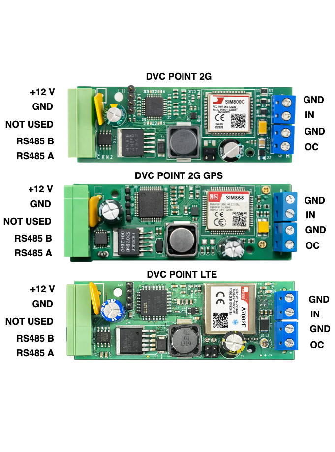
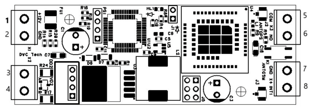
4.1. DVC POINT 2G, 2G-GPS, LTE Models
The pin assignment for DVC POINT 2G, 2G-GPS, LTE is shown in Table 2.
Pin No. | Designation | Function |
|---|---|---|
1 | +V | Modem power supply 7–12V |
2 | GND | |
3 | GND | Common (GND) |
4 | RS-485 “B” | RS-485 interface port |
5 | RS-485 “A” | |
6 | OC | Digital output, open collector |
7 | GND | |
8 | IN | Digital input |
9 | GND |
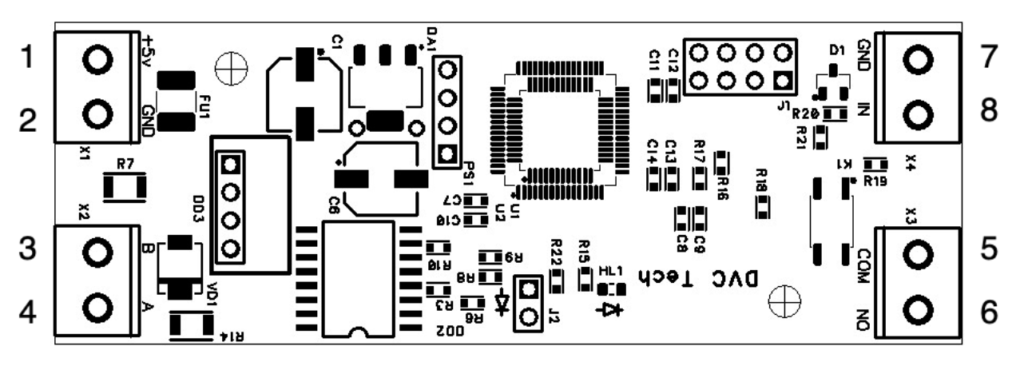
4.2. DVC POINT LTE ISO Models
The pin assignment for DVC POINT LTE ISO is shown in Table 3.
Pin No. | Designation | Function |
|---|---|---|
1 | +V | Modem power supply 7–12V |
2 | GND | |
3 | RS-485 “A” | RS-485 interface port |
4 | RS-485 “B” | |
5 | COM | |
6 | NO | Digital output open collector |
7 | GND | |
8 | IN | Digital input , open collector |
4.3. DVC POINT Wi-Fi ISO Models
The pin assignment for DVC POINT Wi-Fi ISO is shown in Table 4.
Pin No. |
Designation |
Function |
|---|---|---|
1 |
+V |
Modem power supply 7–12V |
2 |
GND |
|
3 |
RS-485 “B” |
RS-485 interface port |
4 |
RS-485 “A” |
RS-485 |
5 |
COM |
|
6 |
NO |
Digital output, open collector |
7 |
GND |
|
8 |
IN |
Digital input |
|
|
|
5. SERVICE MESSAGES
After a successful connection to the server, the modem sends a service packet in the following format:
#DIVISION_M2#867717031557938#17#00000#00000#00000#20211122062211#447483737613#
Service packet structure:
Device name;
Device ID;
Signal level (RSSI);
Latitude (GPS models only*);
Longitude (GPS models only*);
Altitude (GPS models only*);
UTC time (GPS models only*);
SIM card phone number.
Note: For Wi-Fi ISO models, GPS data fields are present in the message structure but are not updated. The SIM card number is displayed only in cellular models.
6. COMMAND PROTOCOL
The device can be configured in three ways:
Via a terminal program, DVC Configurator via the RS-485 interface.
Remotely — by commands sent from the server through an established TCP connection (GPRS/LTE/Wi-Fi).
Remotely — by sending an SMS with the command text to the phone number of the SIM card used in DVC POINT 2G/2G-GPS/LTE/LTE ISO
6.1. Command Format
When sending via RS-485 (CRC field is MANDATORY):
:CMD{ … ;}CRC:XXXX
The CRC field is not checked and may contain arbitrary data (for example, 1234).
When sending via GPRS/LTE/Wi-Fi (from the server):
:CMD{ … ;}
The CRC field is absent in this case.
6.2. FULL LIST OF COMMANDS
PERIOD
Period for sending the standard information message to the server.
Value: integer (seconds).
Default: 60. /this command is currently not used/
In the latest firmware versions, the information message is sent on request
:CMD{INFO:?;}CRC:1234 or
:CMD{DATETIME:?;}CRC:1234
DATETIME
Setting the device date and time.
Format: DD.MM.YY/HH:MM:SS
It is recommended to send the command each time a session is opened.
ALARM
Daily hardware reboot time.
Format: HH:MM.
Default: 14:00.
If the time is not set by the DATETIME command, reboot occurs every 24 hours from the moment of power-on.
IPADDRPORT
Server IP address and port for connection.
Format: “IP”,”PORT”.
Default: “203.161.41.45”,”6050″. / for DVC CLOUD /
SSID_PASSWORD
Wi-Fi network name and password (Wi-Fi ISO model only).
Format: “SSID”,”PASSWORD”.
Default: not set.
BAUDRATE
RS-485 interface communication speed.
Allowed values: 300, 600, 1200, 2400, 4800, 9600, 19200, 38400, 57600, 115200.
Default: 9600.
DATAWIDTH
Number of data bits.
Allowed values: 7, 8.
Default: 8.
STOPBITS
Number of stop bits.
Allowed values: 1, 2.
Default: 1.
PARITY
Parity control.
Allowed values: NONE (none), EVEN (even), ODD (odd).
Default: NONE.
DOUT
Command to close the digital output OC to zero (common) for 2 seconds.
Format: :CMD{DOUT:1;}
Command to close the digital output to zero (common) permanently.
Format: :CMD{DOUT:2;}
Command to open (return) the digital output to 1.
Format: :CMD{DOUT:0;}
Write only. When executed, an unscheduled information message is also sent to the server.
For DVC POINT LTE ISO and DVC POINT Wi-Fi ISO modems, upon receiving these commands, the NO and COM contacts of the optorelay are closed.
? (Parameter request)
Request current values of one or more settings.
Format: :CMD{COMMAND:?;}
or as a group:
:CMD{COMMAND1:?;COMMAND2:?;}
6.3. COMMAND EXAMPLES
6.3.1. Request current parameters
:CMD{BAUDRATE:?;DATAWIDTH:?;STOPBITS:?;PARITY:?;}CRC:1234
6.3.2. RS-485 configuration
:CMD{BAUDRATE:9600;DATAWIDTH:8;STOPBITS:1;PARITY:NONE;}CRC:1234
Set: 9600 baud, 8 bits, 1 stop bit, no parity.
:CMD{BAUDRATE:19200;DATAWIDTH:8;STOPBITS:2;PARITY:EVEN;}CRC:1234
Set: 19200 baud, 8 bits, 2 stop bits, EVEN parity.
6.3.3. Server connection configuration
Standard cloud portal DVC CLOUD:
:CMD{IPADDRPORT:”203.161.41.45″,”6050″;}CRC:1234
Custom server:
:CMD{IPADDRPORT:”192.168.1.100″,”12345″;}CRC:1234
6.3.4. Wi-Fi configuration (Wi-Fi ISO only)
:CMD{SSID_PASSWORD:”nameWi-Fi”,”Wi-FiPassword”;}CRC:1234
6.3.5. Output control
Command from server (without CRC):
:CMD{DOUT:1;}
Command via RS-485:
:CMD{DOUT:1;}CRC:1234
Result: The digital output closes for 2 seconds. At the same time, the device sends an unscheduled information message to the server.
:CMD{DOUT:2;}CRC:1234
Result: The digital output closes permanently. At the same time, the device sends
an unscheduled information message to the server.
:CMD{DOUT:0;}CRC:1234
Result: The digital output opens. At the same time, the device sends an unscheduled information message to the server.
For DVC POINT LTE ISO and DVC POINT Wi-Fi ISO modems, upon receiving these commands, the NO and COM contacts of the optorelay are closed.
6.3.6. Setting time and reboot
:CMD{DATETIME:01.01.26/15:30:00;}CRC:1234
:CMD{ALARM:03.00;}CRC:1234
6.4. COMMAND EXECUTION FEATURES
6.4.1. Operating mode:
For GSM modems, it is better to send configuration commands via RS485 with the SIM card removed, so as not to wait for their execution while the modem attempts to connect to the provider.
6.4.2. IPADDRPORT and SSID_PASSWORD commands:
Are accepted by the device at any time (including during initialization or when there is no connection). After receiving a new command, the modem initializes the network module and attempts to connect to the new address / new network.
6.4.3. Execution confirmation:
Via RS-485: The response is returned to the RS-485 channel.
From the server: Confirmation is received through the communication channel (Wi-Fi/GPRS/LTE).
6.5. TRANSPARENT CHANNEL (DATA TRANSFER)
Any messages that do not match the format :CMD{…;}, do not start with :CMD and do not contain a semicolon before the closing curly brace are treated by the device as user data and are transmitted to the “transparent channel”:
RS-485 → Server: Data received via RS-485 is immediately sent to the open socket.
Server → RS-485: Data received from the socket is immediately transmitted to the RS-485 line.
Important: The device does not analyze or modify packet contents in transparent channel mode.
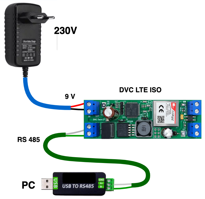
PREPARATION FOR CONFIGURATION
7.1. Adapter connection: Connect terminals A and B of a standard USB – RS485 converter to terminals A and B of the modem and connect the USB connector to the computer.
In Fig. 4 a visual connection diagram of the DVC POINT modem for configuring the main parameters is shown.
7.2. Launching the terminal: Open the DVC Configurator , Serial tab.
7.3. COM port settings on the right side of the program:
* Speed: 9600
* Data bits: 8
* Parity: None
* Stop bits: 1
* Press Open at the bottom to start working.
7.4. SIM card: For 2G/2G GPS /LTE modems, insert an active SIM card into the slot (mini-SIM, located on the back side of the board).
7.5. Wi-Fi ISO: Make sure the access point (router) is powered on, prepare the SSID (network name) and password.
7.6. Power supply: Connect the power wires observing polarity with the power source turned off. Then apply power to the terminals according to Tables 2,3,4.
!! Do not apply voltage higher than 9 V to DVC POINT Wi-Fi ISO !!DV
8. CONFIGURATION AND REGISTRATION
8.1. First Power-On
8.1.1. After power is applied, initialization will begin (~30 seconds); the green indicator will blink.
8.1.2. The Hercules terminal will display the boot stages.
At first power-on, there may be no connection to the server — the message"INITIALIZATION FAILED"will be displayed.8.2. Connection Setup
For 2G / 2G GPS / LTE models:
Send the server configuration command: / by default these settings are already stored in the modem /:CMD{IPADDRPORT:"203.161.41.45","6050";}CRC:1234— for DVC CLOUD,or enter the IP address and port of your own server.
Insert an activated SIM card with a valid data plan.
For Wi-Fi ISO:
Send the command to connect to Wi-Fi and to the DVC CLOUD server::CMD{SSID_PASSWORD:"NETWORK_NAME","PASSWORD";}CRC:1234:CMD{IPADDRPORT:"203.161.41.45","6050";}CRC:1234or enter the IP address and port of your own server.
8.3. Server Registration
8.3.1. Go to https://dvc-cloud.com/
8.3.2. In the cube menu, select Log in, then create a new object.
8.3.3. Add a new device by entering the Device ID number (included in the delivery комплект) and the remaining required data.
8.4. Operating Mode
Upon successful connection to the server:
The green indicator blinks once every 2 seconds.
The terminal displays"INITIALIZATION SUCCESS".If the green indicator blinks once every 0.5 seconds, the modem has not connected to the GSM network. Check that the SIM card is activated and has a valid balance, or verify the correctness of the Wi-Fi network name and password entered for DVC POINT Wi-Fi ISO.
If the green indicator blinks once every 0.2 seconds, the modem has not connected to the server.
If the connection is lost, the device automatically attempts to reconnect every 30 seconds. During this time, the indicator blinks rapidly (once every 200 ms).
After successful connection to https://dvc-cloud.com/,
you can verify modem operation by viewing the received signal level graphs or observing the response when controlling the output.You may immediately configure the modem to your own server, as each modem is tested by us.
9. INSTALLATION AND MAINTENANCE
9.1. Safety Measures
The voltage at the terminals must not exceed 12V for DVC POINT 2G / 2G GPS / LTE / LTE ISO.
The voltage at the terminals must not exceed 9V for DVC POINT Wi-Fi ISO.
All connections must be made only with the power supply disconnected.
Operation in aggressive environments and exposure to moisture are prohibited.
9.2. Installation Recommendations
Cables: Use stranded copper conductors with a cross-section of 0.35–0.75 mm². It is recommended to crimp the wire ends with ferrules.
RS-485 line routing: Route separately from power cables and sources of high-frequency interference.
- SCOPE OF DELIVERY
DVC POINT modem / + sticker with Device ID ! – 1 pc.
Technical passport (this document) – 1 pc.
Individual packaging – 1 pc. - STORAGE AND TRANSPORTATION CONDITIONS
- Storage: In the manufacturer’s packaging at a temperature from -20 to +40 °C, humidity up to 80% .
- Transportation: By any type of covered transport .
- WARRANTY OBLIGATIONS
- Warranty period of operation: 12 months from the date of purchase.
- The warranty applies to defects caused by the manufacturer.
The warranty does not apply in the following cases:
- Violation of operation and installation rules;
- Mechanical damage, traces of exposure to moisture, aggressive environments, insects;
- Unauthorized interference with the design;
- Force majeure circumstances.
Attention: The manufacturer DVC Tech, http://www.division.business reserves the right to make changes to the design that improve performance characteristics without deterioration of the main parameters.
Connection diagram of DVC POINT Wi-Fi ISO to arbitrary equipment